When writing assembly, there may be times when you need to see what's actually going on under the hood. If you are troubleshooting custom shellcode, you need to work through the instructions patiently and deliberately.
This article will look at how to emulate 32-bit ARM shellcode on an x86_64 Ubuntu system. Since most laptops and workstations are not yet running ARM, we need a way to execute non-native instructions on our system. Also, raw shellcode binaries are not in an executable file format that can be run by most tools, so we need a way to execute these files.
Radare2 to the rescue! Radare2 is a console-driven framework that integrates a handy set of tools for binary analysis. You can script these tools together or use the interactive command line interface. One thing I've heard from those getting started with radare2 is that there are a lot of new commands to learn. This is true, but there is an extensive help feature built in and an accompanying ebook available for free:
Radare2:
Radare2 Ebook:
To set this up on Ubuntu, we only need a few simple commands. Official installation instructions are at available at
https://rada.re/n/radare2.html
mkdir ~/github
cd ~/github
git clone https://github.com/radareorg/radare2.git
cd radare2
sys/install.sh
If you already have radare2 installed, make sure you are running a recent version. This tool is actively maintained and regularly updated. Also, there are some bugs prior to the June 2022 release that prevented this example from working.
cd ~/github/radare2
git pull
sys/install.sh
r2 -V
To replicate the shellcode binary we will be working with in this article, you can run the following from a bash prompt:
nemo@hammerhead:~$ echo -n -e '\x01\x30\x8f\xe2\x13\xff\x2f\xe1\x78\x46\x0c\x30\xc0\x46\x01\x90\x49\x1a\x92\x1a\x0b\x27\x01\xdf\x2f\x62\x69\x6e\x2f\x73\x68\x00' > shellcode-696.bin

nemo@hammerhead:~$ md5sum shellcode-696.bin
42ba1c77446594cac3508b940926575d  shellcode-696.bin
Intro to ESIL
Evaluable Strings Intermediate Language (ESIL) is used by radare2 to abstract the instructions from the hardware and create a way to "execute" machine instructions regardless of the underlying hardware. This is ideal for executing non-native assembly instructions in an emulated environment.
To find out more about how radare2 implements ESIL, check out the chapter in the online book on ESIL, available at: https://book.rada.re/disassembling/esil.html
To use ESIL to execute our shellcode we need to do the following:
1. Load our shellcode binary
2. Configure radare2 so that it knows how to interpret our shellcode binary correctly
3. Initialize ESIL
4. Set up registers as needed
5. Step through our assembly instructions to verify their functionality
Executing ARM Shellcode with ESIL
1. Load our shellcode binary
When we run the “file” command on our shellcode binary, we see that Linux cannot determine the file format. Likewise, radare2 cannot determine what it is either.
nemo@hammerhead:~/labs/shellcode/asm$ file shellcode-696.bin
shellcode-696.bin: data
Since it is just a binary blob, we need to specify what it is we're looking at after we load it into radare2. Here we change some analysis and assembly settings so that we can correctly analyze our ARM file:
nemo@hammerhead:~/labs/shellcode/asm$ r2 shellcode-696.bin
[0x00000000]> e anal.arch = arm
[0x00000000]> e asm.arch = arm
[0x00000000]> e asm.bits = 32
[0x00000000]> e anal.armthumb=true
2. Configure radare2 so that it knows how to interpret our shellcode binary correctly
Next we want to specify which instructions are ARM and which are THUMB. I've found that the way to do this is to define functions where the instruction type changes. In this particular shellcode it switches between ARM and THUMB instructions. Therefore we need to do this. If it was all one instruction type, we would just set the asm.bits configuration setting shown above to either 16 or 32.
For a quick definition, you can check out the official ARM documentation [ARM vs THUMB] at https://developer.arm.com/documentation/dui0473/m/overview-of-the-arm-architecture/arm--thumb--and-thumbee-instruction-sets#:~:text=ARM%20instructions%20are%2032%20bits,bit%20instruction%20set%20called%20Thumb
[0x00000000]> af
[0x00000000]> pdf
┌ 8: fcn.00000000 ();
│ rg: 0 (vars 0, args 0)
│ bp: 0 (vars 0, args 0)
│ sp: 0 (vars 0, args 0)
│           0x00000000      01308fe2       add r3, pc, 1
└           0x00000004      13ff2fe1       bx r3
In this snippet of radare2 commands, I am analyzing a function at address 0. We don't really have a function here, but we do this so that we can specify our "functions" as either ARM or THUMB. The “pdf” command just prints the disassembly of the function, which displays the add and bx instructions.
<p>[0x00000000]> s 8
[0x00000008]> af
[0x00000008]> pdf
┌ 24: fcn.00000008 (int32_t arg1, int32_t arg2);
│           ; arg int32_t arg1 @ r0
│           ; arg int32_t arg2 @ r1
│           0x00000008      78460c30       andlo r4, ip, r8, ror r6
│           0x0000000c      c0460190       andls r4, r1, r0, asr 13    ; arg2
│       ┌─< 0x00000010      491a921a       bne 0xfe48693c
│       │   0x00000014      0b2701df       svcle 0x1270b
│       │   0x00000018      2f62696e       cdpvs p2, 6, c6, c9, c15, 1
└       │   0x0000001c      2f736800       rsbeq r7, r8, pc, lsr 6
[0x00000008]> afB 16</p>
The next group of instructions starting at address 8 are THUMB instructions. The “s 8” command will seek 8 bytes into the file and put us where we want to be to define the next and last “function.” After creating the function with “af”, it looks kind of wonky when we try to display it with “pdf.” This is because it is still trying to interpret these instructions as ARM when they should be interpreted as THUMB.
We specify that we want this “function” to be THUMB by setting the number of bits to 16. Under the hood, this is setting asm.bits to 16 for this function only. In a normal ARM binary, radare2 would attempt to make this distinction automatically, but since we have just a blob of shellcode instructions, we need to do this manually.
**Note**
We could cut out the first two instructions and use all-THUMB shellcode. If we did this, we could just set “e asm.bits=16” when we opened the file and wouldn't have to define functions. However, I wanted to show how you can differentiate between the two instruction types if needed.
Radare2 also has a handy way of showing all of the strings in the binary with the “izz” command.
> izz
[Strings]
nth paddr      vaddr      len size section type  string
―――――――――――――――――――――――――――――――――――――――――――――――――――――――
0   0x00000008 0x00000008 4   5            ascii xF\f0
1   0x00000018 0x00000018 7   8            ascii /bin/sh</p>
Now that we have our shellcode binary loaded up correctly, let’s move on to emulation.
3. Initialize ESIL
As mentioned previously, radare2 has a lot of commands, and adding the “?” to a command prefix can be helpful for listing all of the related commands. The “ae?” command will list the commands associated with ESIL and emulation.
[0x00000000]> ae?
Usage: ae[idesr?] [arg]  ESIL code emulation
| ae [expr]                evaluate ESIL expression
| ae?                      show this help
| ae??                     show ESIL help
| aea[f] [count]           analyse n esil instructions accesses (regs, mem..)
| aeA[f] [count]           analyse n bytes for their esil accesses (regs, mem..)
| aeb ([addr])             emulate block in current or given address
| aeC[arg0 arg1..] @ addr  appcall in esil
| aec[?]                   continue until ^C
| aef [addr]               emulate function
| aefa [addr]              emulate function to find out args in given or current offset
| aeg [expr]               esil data flow graph
| aegf [expr] [register]   esil data flow graph filter
| aei[?]                   initialize ESIL VM state (aei- to deinitialize)
| aek[?] [query]           perform sdb query on ESIL.info
| aeL                      list ESIL plugins
| aep[?] [addr]            manage esil pin hooks (see “e cmd.esil.pin”)
| aepc [addr]              change esil PC to this address
| aer[?] [..]              handle ESIL registers like “ar” or “dr” does
| aes[?]                   perform emulated debugger step
| aets[?]                  esil Trace session
| aev [esil]        visual esil debugger for the given expression or current instruction
| aex [hex]                evaluate opcode expression
To use emulation, we first need to initialize ESIL with the “aei” command. After that we initialize a stack. Radare2 will pick a stack location automatically, but this can be changed by specifying the address as a parameter to the “aeim” command.
[0x00000008]> aei
[0x00000008]> aeim
4. Set up registers as needed
Since our shellcode instructions start at zero, we will set our Program Counter (PC) to zero with “aepc 0” command. If we wanted to start execution at a location other than offset 0, we could do that by setting the start address with “aepc <address>”.
[0x00000008]> aepc 0
Since this Position Independent Code (PIC), there is nothing else we need to do. However, one of the instructions in our shellcode (“subs r1, r1, r1”) sets r1 to 0. Since this register is already zero by default, let’s set it to 0xffff so that we can see the change take place as we step through the shellcode. To do this, we use the “aer” command.
[0x00000008]> aer r1 = 0xffff
5. Step through our assembly instructions to verify their functionality
Alright, we have things set up. Let’s switch into visual mode and go to the debugger panel. There are multiple options (panels) in visual mode so we will need to hit “p” twice to get to the correct panel. If you want to exit visual mode at any time, just hit the escape key. You can also hit “?” for a list of available commands. For more information on visual mode, check out the section of the radare2 book on this topic: https://book.rada.re/visual_mode/intro.html
[0x00000008]> V
(hit “p” twice to get to the debugger panel)
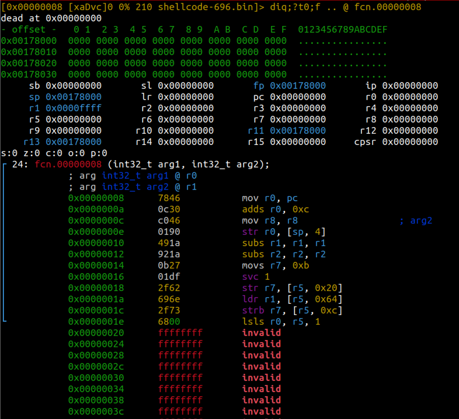
When you are on the right panel, you will notice a set of registers near the top. It will look something like this:
Any r2 commands that you normally enter via the console can also be entered while in visual mode. To do this, hit the colon “:” key and you will get a “>” prompt at the bottom of the screen. Enter any commands you want to run and hit enter. Hit enter again with no input to exit the command line. For example, if we wanted to print the string at offset 0x18, we could do the following:
# Hit “:” while in visual mode.

> ps @0x18
/bin/sh
> # Hit enter on a blank line to return to visual mode.
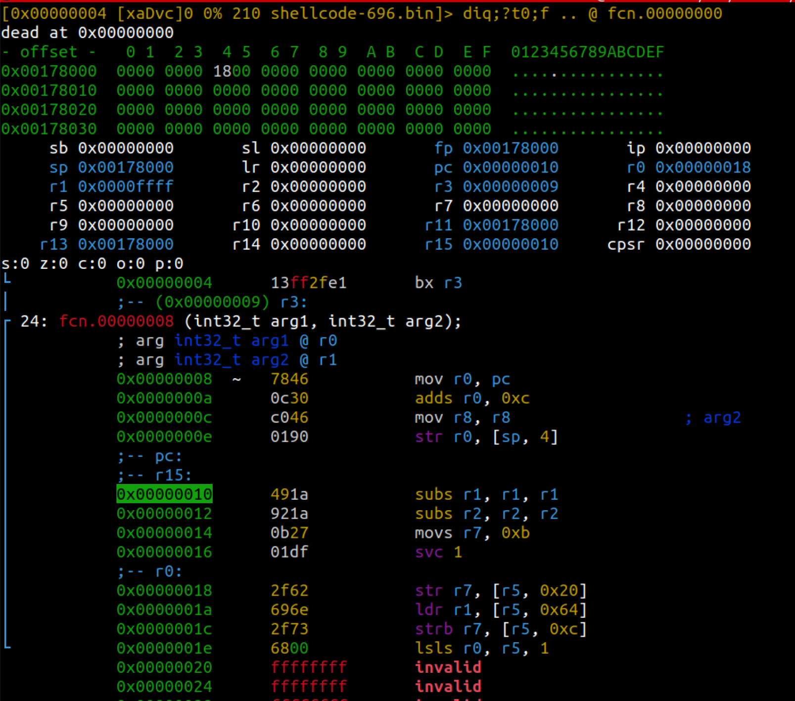
Now we can start stepping through the assembly instructions by hitting the “s” key. As you step through, you will notice that the registers at the top get updated along with the stack data (starts at 0x00178000 in the first image). You will also notice that the address of the next instruction to be executed (aka PC) is highlighted in the assembly instructions (0x00000010 in the first image)
Notice that the image above shows that the r1 register holds 0x0000ffff. Also notice that the next instruction to be executed will be “subs r1, r1, r1”. This instruction will subtract r1 from itself and store it back into r1, essentially making it 0.
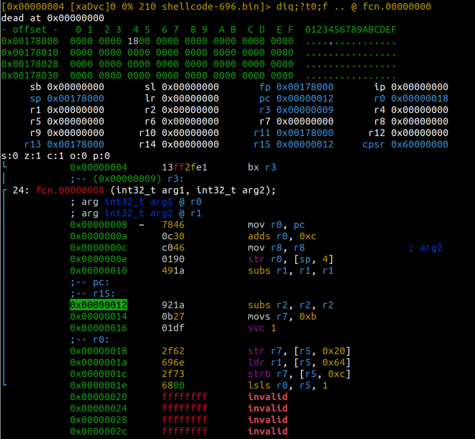
Step to the next instruction by hitting the “s” key again.
Notice that we are on the next instruction and r1 has been set to 0.
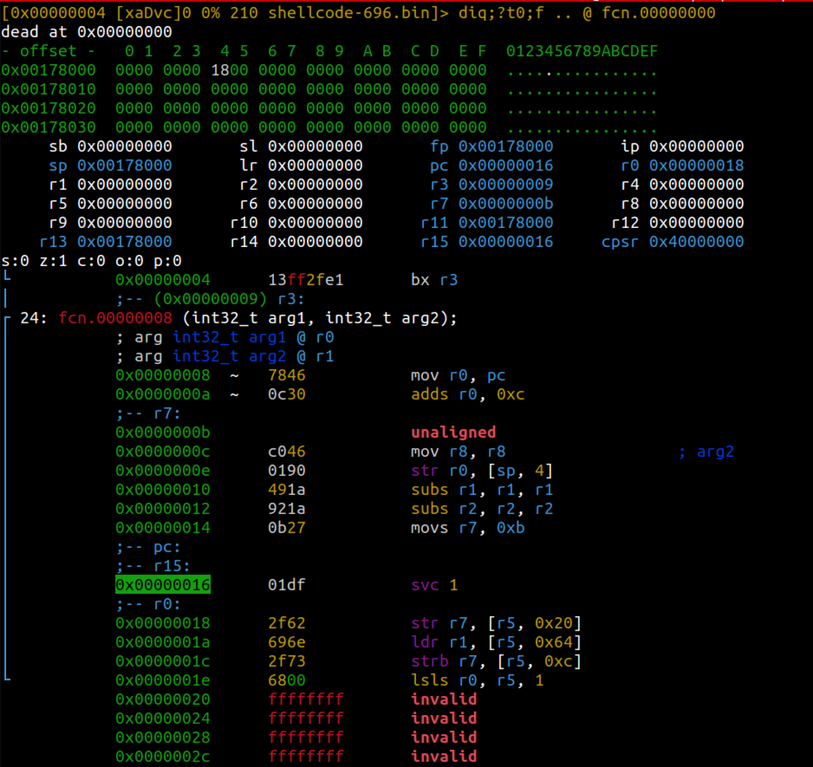
Continue stepping until you get to the “svc 1” instruction. At this point, we have determined that our shellcode will execute correctly. If there were any problems with our ARM assembly, we would have seen them as we stepped through the instructions one by one.
Now everything is set up to make the supervisor call via the “svc 1” instruction. We are making an “execve” call, so we should have 0xb in the r7 register. The first parameter in r0 should be a pointer to the path of the binary we want to execute. We see that r0 holds 0x18. We can verify what that points to by running the following commands:
# Hit “:” while at the “svc 1” instruction in visual mode.

> ps @r0
/bin/sh
>
We are not passing any arguments to “/bin/sh” and we are not setting any environment variables, so we can verify that both r1 and r2 are set to zero.
Since we are not running on an ARM system, we cannot correctly execute the supervisor call (“svc 1”) instruction. Keep this in mind when you are testing more complex shellcode. Even though we cannot execute the supervisor call, this technique allows us to walk through and troubleshoot our ARM assembly step by step.
Conclusion
Whether you are troubleshooting custom shellcode or trying to verify what you are seeing statically, sometimes you just need to see what the instructions are actually doing. Radare2 allows you to load up non-native assembly from an unknown file format (such as a shellcode binary file or a firmware image) and walk through the instructions step by step.


